Where to Find the Best Assembly Programming Project Help in the UKAssembly programming has been a challenge for many students and so are homework and projects that require knowledge of assembly programming. The highly technical nature of assembly languages makes them the most feared languages in pro...
Building a Specific Pattern
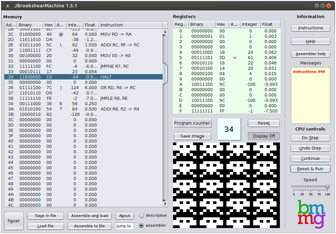
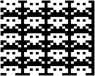
The following is the algorithm used to build the pattern. We will use a pattern consisting of 8 by 7 bits saved as data Set initial display address in RD Repeat 7 times: (number of rows in the pattern) Load RA with RD Repeat while address in RA is < FF: Repeat 4 times: (number of times that a pattern fits in a display row) Load the current byte of the pattern Save in current display address Increment display address in RA by 24 to go to the next repeated row Increment RD to advance to next display row Increment current byte of pattern to get the next pattern row The algorithm solves the problem by printing every row in the pattern repeatedly, 4 times in a display row, and then until we reach the end of the display, incrementing by the pattern height times display row size each time.
Description


Technical Description
R1 and RF are used to increment and decrement counters, respectively. R4 is used to count the number of patterns per display row, which is 4 since the patterns are 8 bits of width and the display has 32 bits per row. R8 is the separation between repeated patterns in different display rows since the patterns are 7 rows of height and each row in the display has 4 patterns, then the next pattern repetition is at 4*7 =28 bytes below since we need to go to the next repeated row after we have displayed a row of 4 patterns, then we only need to increment 28-4=24 to go to the next repeated row, since 24 is 18 in hexadecimal, that is the value we put in R8. The values in R6 and R7 are necessary to use the JMPNE and JMPGT instructions, which require the jump address to be saved in a register. The program goes through three nested loops to print the pattern. The outer loop is for printing each row in the pattern, since the pattern has 7 rows, we have to loop 7 times, the counter for this loop is RC, and we initialize it to 7, we keep track of the current row pattern in R5 that has the address of the current row in the pattern. At the start, R5 is loaded with the address of the pattern. After all the processing is done for the RC loop, we increase the pattern row, which is held in R5 and we decrement RC, if it’s not zero we repeat the cycle, otherwise, we end the program. The following loop is nested inside the RC loop. This next loop is used to go through repeated rows in the display. The counter for this loop is the register RA, which initially is loaded with the start display address. After all the processing within the loop is completed, the value of RA is incremented by 24 to go to the next repeated row, if after incrementing RA we wrap around, that is, we end with a value lower than 24, then we end the RA loop and continue with updating the variables of the outer RC loop. The innermost loop is the one that prints 4 times the current pattern in a display row. The counter for this loop is held in R3. Inside the loop, R0 is loaded with the current pattern row, which is at the address given in R5, then the pattern is copied to the current display address, which is in RA, then the display address is incremented by one to point to the next display position and the loop counter is decremented by one if the counter is not zero the process repeats to print all 4 patterns in a row. Otherwise, it ends the R3 loop and continues with the updating of the RA loop.
